Ram Truck No Splice Kill Switch Harness Instructions
**Please read these basic instructions completely to ensure you are aware of the overall steps as well as any additional details for accessing the area you have selected to hide your kill switch before you begin. This installation isn’t difficult as long as you know how to gain access to the area where you want to hide your kill switch. There are multiple videos online to help access various panels within your dash/console/etc online to reference. Please utilize those to prepare for your installation.
Items to consider:
- Only you know the risk you are facing for which you are now taking an extra step to help safeguard the vehicle you own.
- This solution is a deterrent to thieves being able to steal your vehicle. If a thief REALLY wants your vehicle, they will find a way to get it. So think of your security as layers of an onion, which always has more than one. Could be simple steps, but maybe not do to the threat and/or risk you are facing.
- You alone must decide where to place the hidden kill switch in a location that you find acceptable to access for each time you need to activate the hidden kill switch.
- The harder it is to see the hidden kill switch the better. Be creative.
- There is a balance between hard to find/reach, and it being frustrating for the owner themselves every time they use their vehicle. Your vehicle, your choice. No choice is wrong.
- Please do NOT share your hidden kill switch location with anyone. It’s great to give general suggestions for options on where to install, but if online just because someone has an account doesn’t mean anything.
- Creative item some have done:
- Chaining more than a couple hidden kill switches together and mounting them in the same area where they are all hidden. Only the owner knows the direction the on/off part goes for each one as they were physically mounted different ways (not all off positions going in the same direction – and hidden so done by feel). Kind of like a combo lock!
- Last recommendations:
- Each harness connector at the ignition switch should go back together and make a “click” sound when properly connected. Click sound won’t be too loud, so turn down the music to listen for it. 🙂 It could drive you crazy when you test this and it doesn’t work due to one connector not fully seated. There are only a couple so it won’t take long for this step.
- For the safest method, disconnect your negative battery terminal before starting any installation steps.
- VERY IMPORTANT: *****Once you have fully installed all of the wiring and the switch is connected in its hidden location – TEST the hidden kill switch before you put the panels back on the dash!
Video’s to watch depending on which generation of Ram Truck you have – NOTE: **You do NOT have to remove the ignition switch from / out of the dash to install this harness, simply disconnect and then reconnect harness from back side of the ignition switch. These video’s are basically to show how to remove the kick plate below your steering wheel – you can watch the rest of the video to learn more, but those additional steps are not needed:
4th Gen Video – Coming soon, basically the same as 5th gen except push to start button hole is located in this kick plate vs. 5th Gen Ram Trucks is just above this kick plate on top right side.
5th Gen Video – Also shows how to change to a RED Push button start for 5th Gen Trucks!
Installation steps:
4th Gen: Using a 7mm nut driver or socket wrench.
5th Gen: Using a 7 or 8mm nut driver or socket Wrench.
– remove the 2 bottom screws under the steering wheel bottom access panel.
4th Gen: Then gently remove that cover by pulling from bottom towards drivers seat to release the clips on each side on edge. Then pushing slightly up and back towards you while keeping the clips you just released on back side of panel out of their previous holes and the entire panel will come off. Be careful not to loose the plastic ring around the ignition. Usually silver in color.
5th Gen: As seen in video link above, there are clips holding your lower kick panel in place, work your way around to release them.
– The OBD2 socket connector and wiring will still be attached to the cover you are removing, so just put the bottom panel straight down on the floorboard.
Remove any additional panels necessary in order to route your harness lead(s) to each hidden kill switch location you intend to mount each kill switch(s). Mentioned at beginning – There are many videos online for other work that has been shown how to get into those panels/consoles/etc. Please reference a component in the area where you decide to hide your kill switch and look up one of those videos to see how to access that area of your vehicles dash/console/etc.
Once you have all access panels removed, install the kill switch harness so that the connector ends are just behind the push to start (or turn to start FOB start if that is what you have) switch. Do NOT connect the connectors yet, that step will come later.
Now secure the hidden kill switch(s) and connect the two 4.8 or 6.3mm ends that are heat shrink wrapped on to the back side of the switch (assuming you purchased them – or similar approach you took). Unless you selected the solder option (wires pre-soldered to switch) where now you would complete soldering the wires in. There is NO wrong way to wire in the switch, no wires to cross connect wrong. The switch simply allows or does not allow the connect to complete depending whether it’s in the On or Off position. So no worries in doing this step wrong.
Ensure you have all hidden kill switches securely mounted with the harness ends fully mounted to the hidden kill switches.
Connect the connector ends on the kill switch harness is now next: While looking under the steering wheel in the panel area you removed under it, look up in the top right area of the opening, towards your ignition switch (either key style fob or push to start button – whichever one you have) and find the connector that goes into the back of the ignition switch. It is identical to the female end on the no splice kill switch harness for easy identification.
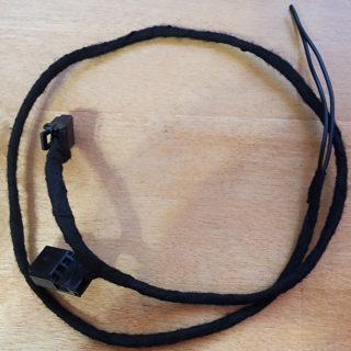
Pic of female end:

As seen in the above picture, there is a squeeze tab release on the female connector to release the connector from the back of the ignition switch. Squeeze it while pulling away from the ignition (towards front of truck direction, and down a little) and it should easily separate. If it is not disconnecting, please ensure the squeeze tab is fully depressed in while pulling it out.
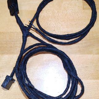
You should now have something that looks similar to this – note in picture the female end is disconnected now:

Now take the no splice kill switch harness and connect the male connector into the female connector you just removed from the back of the ignition switch, and on the other end of the harness you are installing put that female connector into the back of the ignition switch. In short, you are installing the no spice kill switch harness in-between where you disconnected the truck harness from the back side of the ignition switch in your dash.
Dress up your cabling and secure it to your liking – making sure nothing rubs or rattles.
Time to test! Before putting your panels back together, test it!
Now that you know it works, secure any remaining wiring needed, and reverse steps for replacing panels/console/etc that were removed for access during the installation process.
You’re finished with the installation!
Congratulations! This was an easy installation wasn’t it? Many spend more time deciding where to hide their kill switch than it takes to complete the installation TBH.
For those finding these instructions and wondering where to order one of these for your 4th/5th Gen Ram Truck – Here’s the LINK